Four Different Types of Illuminations in a Single Scan
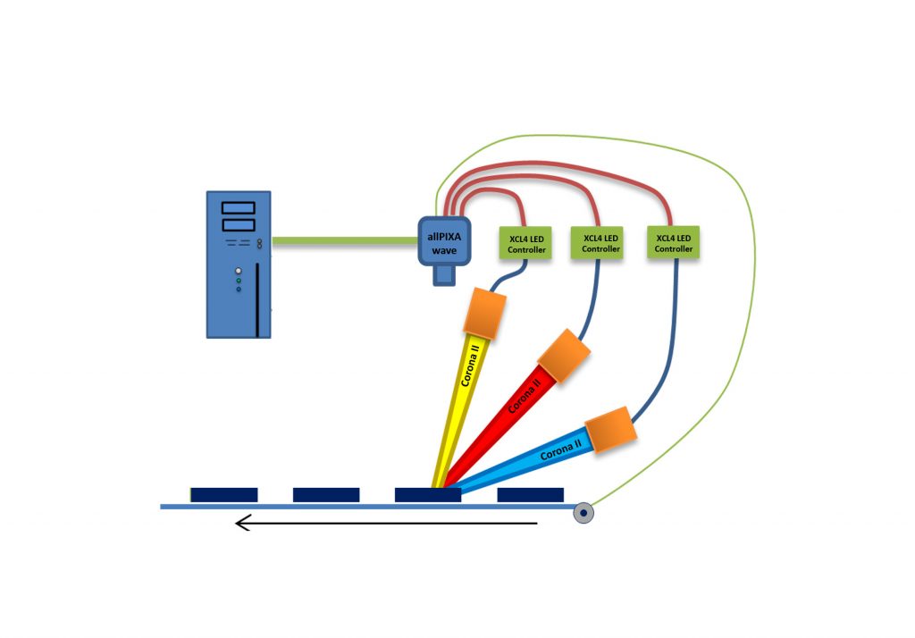
Different allPixa cameras can be used to trigger up to four different flash controller channels synchronized to its line acquisition. This can be used to acquire several images with different illumination geometries (dark field, bright field, or backlight, co-axial) and/or colors (white, red, green, UV, IR) simultaneously in only one scan by line-multiplexing.
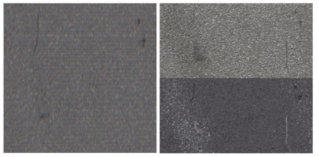
Image 1 | Flash mode acquisition of metal sample with two different illumination geometries.
Left: raw camera output. Right: Separated individual images with color plane correction. (Bild: Chromasens GmbH)
This means multi-channel flashing enables the system to scan the object using with up to four different type of illuminations in a single scan. Various types of defects are possible to be captured with this kind of vision system. Examples are cracks, scratches, stains, chipping, etc. The multi-channel flash control feature of the cameras can acquire multiple images, whereas every image is recorded under different illumination conditions in a single scan. In addition, high color fidelity and a high dynamic range help to achieve excellent results in defect detection. The high-quality color images can give more information about the defect class and extent of the defects on the object. The large full well capacity of the sensor enables a high dynamic range and the blooming resistance is outstanding, which is very import for strong local reflections in bright field configuration.
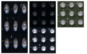
Image 3 | HDR demonstration on ball grid array sample.
Left: Interlaced image.
Middle: Separated images with different exposure times. Right: HDR image. (Bild: Chromasens GmbH)
Flash Controller Synchronization
One application where this is useful is in inspection tasks where different kinds of defects are identified either in images captured with brightfield illumination (e.g. scratches) while other defects require darkfield illumination (e.g. dust particles). Figure 1 illustrates this: The left side shows the raw camera image output for a metal sample with activated flash mode for one brightfield and one darkfield illumination. The size of this image in scan direction is enlarged by a factor of two as each line is captured twice with alternating illumination. The result is an image that is interlaced line by line repeatedly. This image needs to be deinterlaced and a correction for the color plane shift needs to be applied which results in the images shown on the right. The separation of these images is not part of the camera function and needs to be done in a postprocessing step.
Multi-exposure HDR Imaging
The flash mode of the allPixa pro, allPixa wave and allPixa evo cameras allows to capture multi-exposure images during a single scan. This results in several congruent images of the same scene with different integration times. Such a set of images is the prerequisite needed to compose a single HDR image. The general goal of HDR imaging is to reduce the loss of detail from imaging scenes containing regions with vastly different brightness. With a single image, one can either use a low integration time which loses information in the dark regions due to camera noise or a higher integration time which leads to saturation in the bright regions. But if the images from both (or more) exposure times are available it is possible to optimally compress this information into the standard dynamic range of a digital image. The flash mode of the allPixa series cameras is implemented in such a way that the integration time during each pattern is determined by the resulting time of the pattern. So, for HDR imaging set up the flash patterns in such a way that the resulting times of the patterns matches the needed different exposure times. This will create an interlaced image like the one shown in Figure 1 but with different exposure times instead of different illumination geometries. Figure 3 demonstrates it using a ball grid array (BGA) sample. The solder balls are made of highly reflective metal while the base of the sample is usually quite dark. The HDR approach allows to inspect the base for defects without saturating the balls. There exist multiple ways of computing HDR images from multiple low-dynamic range images.
Multi-Channel-Flash
The master slave mode for allPixa series of cameras is two or more cameras are synchronised in such a way that each line is captured at exactly same moment in both or more cameras. In this mode, one of the cameras is the master which receives the encoder signal and controls other cameras. Multi-channel Flash mode is fully compatible with master/slave operation of the allPixa series of cameras, 3D Pixa cameras. It is recommended to use a dedicated frame trigger. For a 3DPixa with internal master/slave interface you can send the trigger signals to the camera using the Camera Link signals as this will free up the external interface for flashing. Otherwise the external interface is already in use for the synchronization cable so to access the pins sending the flash signals you need a suitable breakout cable.

